Why using those “speakers” ? #
This is a great starting point! I know this -Logitech Z906- audio system is considered as garbage by the hifi community, but I’ve been using it since 2013 (time pass) and I’m quite happy with. I know, there’s no HDMI-ARC I/O, no CEC, and it breaks easily. I mean, look at this power supply?
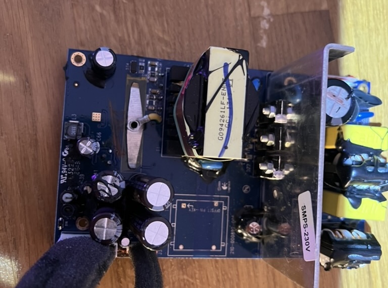
I had to repair it multiple times because factory components heat up a lot and it causes the system to pop loudly during use, or it simply doesn’t start. Fortunately, I have all the necessary equipment at home to work on electronic and it’s quite easy to repair when you have the nomenclature.
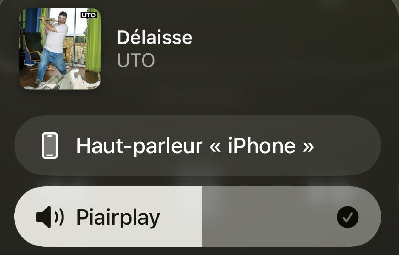
I hate throwing objects when the repair costs less than few bucks (which is mostly the case). But this system is not convenient at all as it was made for using it with a computer, not as a living-room sound system. When I wanted to listen to music, I had to turn on my TV (connected via S/PDIF), then use the Spotify app, and adjust the volume using its remote control. It was “fine” during a time, but I noticed that my TV draws 120 W of power. What made me decide to tweak this system was that I switched to Apple Music —there being no Android TV app— which meant I couldn’t use it for listening to music :(
Adding Airplay functionnality #
Ok, so the first thing to do is simply use Airplay, right? But how?
That’s where I love the open-source community 🤍
First test #
I have a bunch of Raspberry Pi sitting on my desk, and I did not know what to do with them since most of my home services are on my homelab. So I grabbed the less power hungry -and less powerful- RasPi I had (4B), looked on GitHub for Airplay projects, and found this. Quickly runned a test, connect it on 3.5 mm input and voilà!
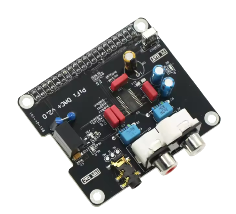
Unfortunately, RasPi’s built-in audio jack output sounds quite awful. To make things better, just add an external DAC such as the PiFi DAC+ v2.0:
Use external DAC #
Raspbian (RaspberryPi Linux based distro) uses alsa as audio driver. Using an external DAC requires some configuration to use it as the default output. First, connect via SSH and check if your DAC is correctly detected:
$ cat /proc/asound/cards

 0 [Headphones     ]: bcm2835_headpho - bcm2835 Headphones
                      bcm2835 Headphones
 1 [sndrpihifiberry]: HifiberryDacp - snd_rpi_hifiberry_dacplus
                      snd_rpi_hifiberry_dacplus
 2 [vc4hdmi        ]: vc4-hdmi - vc4-hdmi
                      vc4-hdmi
As you can see, there’s three audio outputs: built-in jack, DAC and HDMI. To use output n°1 (DAC) as default, do:
# touch /etc/asound.conf
# nano /etc/asound.conf

    defaults.pcm.card 1
    defaults.ctl.card 1
then restart your Pi. Try using Airplay, it should play sound on DAC’s output.
Being lazy requires work #
So far, so good, you’ve added AirPlay connectivity to your speakers really easily. But who wants to get out of the couch, turn on the audio system, change input and set volume? I certainly would not.
Furthermore, I lost my Z906’s remote, so I need to use my Shield TV remote to turn on/off the system, but it also turn on the TV. The solution would be to control everything through Home Assistant. This will allow us to create automation with Airplay.
Configure Shairport-Sync #
If you followed this guide to install shairport-sync on your Pi, at the Build and install step, change the configuration flags to add MQTT functionnalities:
$ git clone https://github.com/mikebrady/shairport-sync.git
$ cd shairport-sync
$ autoreconf -fi
$ ./configure --sysconfdir=/etc --with-alsa \
    --with-soxr --with-avahi --with-ssl=openssl --with-systemd --with-airplay-2 --with-mqtt-client
$ make
# make install
The flag --with-mqtt-client should use the auto-discovery method and appears automatically in your Home Assistant devices under MQTT.
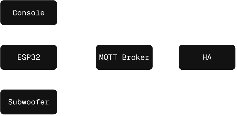
Control the Z906 with an ESP32 #
The Logitech Z906 works as follow: the main system is located inside the subwoofer, and control commands are done via the console. In order to catch and emulate commands, we need to be between the console and the sub. Thanks to nomis’s work and zarpli’s work who reverse-engineered, lots of people understood how to interface with the system using any device with serial communication capabilities, such as Pi, ESP 32/8266, Arduino and so on.
This project does exactly what I wanted: intercept commands and send them via MQTT.
Nevertheless, there isn’t any functionality to turn it on/off, since that requires some soldering.
Add power control #
First thing to do is modify Jupsi’s code to add power functions. I’ll not cover every modifications, but there’s two important things to cover: autodiscovery and power handler. Using serial commands to control power is not possible, we’ll need to simulate a press on the power button located in front of the console.
To display a power button on Home Assistant, we need to tell our MQTT Broker that there’s such functionnality by adding this function to z906_autodiscover.cpp:
void Z906::_AutoDiscovery_Power_Button(MQTT *mqttClient) {
  StaticJsonDocument<512> doc = Z906::_Helper_BuildBaseAutoDisocvery(
    "Power Button",
    "Z906_Power_Button",
    "homeassistant/button/z906/power_button/state",
    "homeassistant/button/z906/power_button/set");
  String payload;
  serializeJson(doc, payload);
  mqttClient->Publish("homeassistant/button/power_button/config", payload.c_str(), true);
}
This will return the power state and control.
Next, we need to handle MQTT message to control GPIO on our ESP32. To do this, I modified z906_onmqttmessage.cpp:
void Z906::_OnMQTTMessage_SetPower_Button(MQTT* mqttClient, const char* message) {
  //Power Button Broker Message Handle
  Serial.println("Power Button Pressed");

  //Trigger the Power Button
  digitalWrite(POWER_PIN, HIGH);
  delay(300);
  digitalWrite(POWER_PIN, LOW);
}
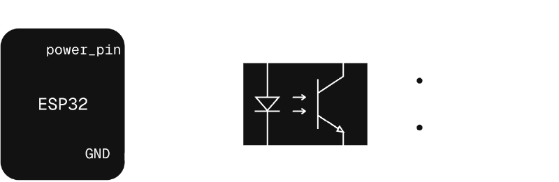
This will simply close our circuit between POWER_PIN and GND, simulating a pressed button. Unfortunately, we cannot directly solder our ESP32 to the power button. The proper way to do this is by using an optocoupler (a basic PC817 for example) to completely isolate both systems, as current going through the power pin and ground could damage the console:
You can look at the project on the GitHub repo:
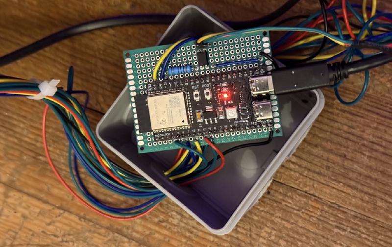
Connect everything #
Now that we have our code and our schematic, time to inhale soldering tin’s smoke (I know it’s not good for me but don’t worry, my fan was besides me)! This took quite a moment as there is a lot of cable, and DE-15 connector were cheap, so the quality was not there, but I managed to do everything:
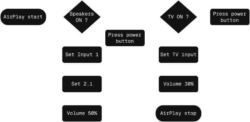
Make some automations #
AirPlay remote control and state ? Check
Logitech Z906 remote control and state ? Check
The only thing left to do is simply automate the process using Home Assistant, which is very easily with latest versions. The flowchart is as below:
That’s it ! #
Everything is done ! I did more automations, especially turning it off when I’m leaving home or put my headphones. There’s a lot of possibility : building a multiroom audio system by making my own speakers, use the Z906 as an alarm siren (trust me, it can be reaaally loud), or even install Music Assistant as a docker container on my homelab and manage my own music library while connecting all my different services.
I’m really happy to have integrated those speakers into my home automation system, and I’ll add or modify more and more of what I own for greater laziness ;)